Having moved so often growing up, I was nevr part of a neighborhood gruop of guys playing games, and so was never into sports. Instead I followed my father’s interesets in things technical.
I was into electronics. I built two or three oscilloscopes, using war surplus CRTs that were cheap. I built several other electronic items. I wanted to be an amateur radio operatior, but you had to read Morse code at 13 words per minute, and I could never get that fast. I loved listening to short wave stations from all over the world. Unfortunately, I have no photos.
I dabbled in photography, and had a 35mm camera, as well as Dad’s bellows camera.
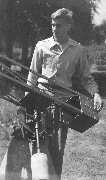
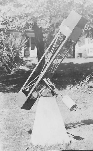
I also was into astronomy. I built an 8″ reflector – grinding a 6″ mirror first at the Franklin Institute in Philadelphia, and finishing it at home. Then I was given an 8″ finished mirror. Dad arranged for applying an aluminum coating on the mirror. I made the mount at the Institute, and Dad helped me pour a concrete support and cast an aluminum holder for the mirror. I made the rest. I was especially proud of a drive system I invented.
Back to Hobbies
DESCRIPTION OF THE EIGHT INCH TELESCOPE
(written at the time)
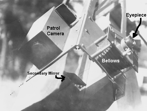
The telescope is an eight inch F/8 Newtonian, with attachments for photographing at the prime focus. The mirror is mounted in a cast aluminum cell at the base of the frame, which is made of aluminum angles and 9” x 9” x 1/8” aluminum plates. The light shield at the top end is Masonite. A ¼” aluminum plate on the side has four holes corresponding to four bolts silver-soldered to the mounting. It takes about one minute to carry the telescope out, set it on the mounting, and screw down the four wing nuts.
The mounting is an “AAFI (Amateur Astronomers of the Franklin Institute [Philadelphia]) Pillow Block Mounting”. It is made of cold rolled steel with 1 ½” steel axes.
There are setting circles in right ascension and declination.
The original drive was a large gear cut in aluminum with a ¼-20 tap. The worm was turned by a ½ RPM motor. The system suffered two problems – it was shy about ten teeth and ran too fast, and it had an oscillation due to an uneven worm. Although it was excellent for visual work, it was useless for photographic work.
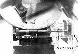
A new system was devised, using a 4 RPM heavy duty Telechron motor driving a 60:1 worm and an 8:1 spur. These in turn drive a friction coupled brass pulley with a small groove accurately cut in it. A fine steel wire connects the pulley with a large bakelite pulley on the polar axis. The ratio is 120:1436.0681833.
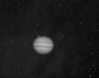
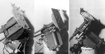
Instead of a conventional eyepiece holder, a camera attachment is at the prime focus. IT si simply a flat metal plate with a 2 ½ x 3 ½ inch hole The plate can be moved by four screws to make it perpendicular to the optical axis, and to place it exactly at the flocal plane. A Graphic cut film holder is clamped over the hole.
The purpose of the bellows is to keep out stray light.
For visual work, a metal plate containing the eyepiece is clamped in place of the film holder at the prime focus. In a similar manner, a spectroscope or photometer might be clamped at the prime focus.
On the inside of the telescope, a sheet of thin aluminum with a 2 ½ x 3 ½ inch hole slides in a track past the opening to the bellows. This serves as a focal plane shutter for both instant and long exposures. When a small slot is used, very high speeds can be obtained by snapping the slot past the opening.
Filter posts list
Search Posts:
